True Bypass vs Buffered Bypass Guitar Pedals: A Wholesale Buyer’s Guide
Compare true bypass and buffered bypass guitar pedals by signal loading, switching, noise, testing and batch control for wholesale sourcing.
Quick answer: A true-bypass pedal generally routes the input to the output through a mechanical or relay switching path when the effect is off, while a buffered-bypass pedal keeps an active buffer in the signal path. True bypass can remove the effect circuit from the bypassed path, but a long cable and several connections can still load a passive guitar signal. A well-designed buffer can help drive cables and later pedals, but a poor buffer can add noise, distortion or an unwanted level change. Neither choice is automatically better for every pedalboard or wholesale range.
For an importer, distributor or private-label buyer, bypass type affects circuit design, footswitch or relay selection, power-loss behavior, pop noise, input and output impedance, packaging claims and quality testing. It should be specified and verified rather than treated as a decorative badge.
This guide explains how to compare true and buffered bypass for sourcing decisions. It focuses on measurable behavior, controlled listening, production checks and the information needed in an RFQ. Exact performance depends on the selected circuit and complete signal chain.
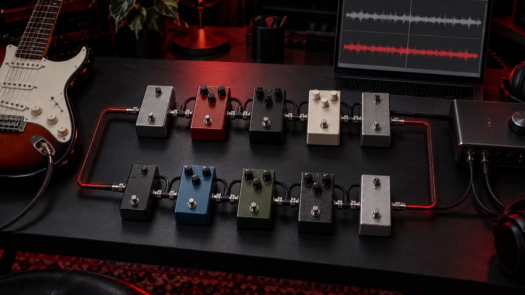
Editorial illustration: the useful comparison covers the whole cable-and-pedal chain, not one footswitch in isolation.
Define what “bypass” means in the proposed pedal
Ask the supplier for a circuit-level description. “True bypass” may use a multi-pole mechanical footswitch, a relay controlled by electronics or another arrangement that disconnects the effect circuit from the audio path. “Buffered bypass” can describe many active topologies with different input impedance, output impedance, gain, headroom and power requirements.
The RFQ should state:
- Required bypass architecture and switching method.
- Whether the bypassed level must be unity within a defined tolerance.
- Input and output impedance targets or approved ranges.
- Supply voltage, polarity and allowable current consumption.
- Required behavior when power is removed or voltage falls.
- Acceptable switching noise and temporary signal interruption.
- LED behavior and whether it depends on external power.
- Cable lengths and source/load used for validation.
- Whether the pedal must preserve audio in bypass if power fails.
These details prevent a label from substituting for a performance specification.
How true bypass works in practice
In a common mechanical true-bypass design, the footswitch changes several contacts so that the input connects directly to the output when the effect is off. The effect circuit is disconnected from the main audio path. This can be useful where the buyer wants the bypassed pedal to contribute minimal active circuitry.
However, true bypass does not make the entire board electrically invisible. The guitar still sees the input cable, output cable, patch leads, connectors and capacitance of the chain. With passive pickups, long total cable length can reduce high-frequency content. Multiple mechanical contacts can also develop wear, contamination or intermittent behavior if component and assembly quality are poor.
True-bypass pedals often use a 3PDT-style footswitch when one pole controls an indicator. Relay-based true bypass can provide different switching feel and logic, but it adds a control circuit and power-behavior questions. The buyer should specify the actual implementation rather than assuming every true-bypass pedal is identical.
How buffered bypass works in practice
A buffer presents a defined input load to the source and provides a lower-impedance output to drive the next cable or device. In a suitable design, this can reduce the effect of downstream cable capacitance and make the signal less sensitive to later loading. A buffer can be especially relevant when a pedalboard uses long cables or many connections.
The result depends on the circuit. Input impedance that is too low can load passive pickups. Insufficient headroom can clip a strong signal. Poor power filtering or layout can add noise. A level offset can make bypass comparisons misleading. The buyer should evaluate input loading, output drive, noise, distortion and power behavior under defined conditions.
Some effect circuits already contain an always-on input or output stage; others use a separate buffer. Ask whether the buffer is active only in bypass or shared with the effect path, and whether the design changes phase or level.
The cable-loading problem
A passive guitar pickup, guitar controls and cable form an interacting electrical system. Cable capacitance increases with construction and length. A long cable can shift or reduce high-frequency response before the signal reaches an amplifier. Several short patch cables also contribute.
A true-bypass chain may work well with a compact board and short total cable length, while a larger board may benefit from a correctly placed buffer. That does not mean every buffered pedal should be first in the chain. Some fuzz or other circuits are intentionally designed to interact directly with passive pickups and may respond differently after a buffer.
For a wholesale guide or product manual, avoid rules such as “always put the buffer first.” Explain that signal-chain order should be tested with the player’s pedals, guitar and cable lengths.
Compare observable performance
| Area | True-bypass questions | Buffered-bypass questions |
|---|---|---|
| Bypassed path | Contact resistance, continuity and isolation | Input load, output drive and level |
| Power removed | Does audio still pass as specified? | Does audio mute, distort or pass? |
| Switching | Mechanical/relay noise and interruption | Electronic/mechanical noise and interruption |
| Long cables | Total cable loading remains | Buffer may reduce downstream loading |
| Noise | Contacts, wiring and grounding | Circuit noise, power filtering and grounding |
| Reliability | Footswitch or relay cycle performance | Switching parts plus active circuit stability |
The table is a test plan, not a verdict. A well-executed example of either architecture can be appropriate.
Input impedance, output impedance and headroom
If the supplier publishes impedance values, request the measurement conditions. Input impedance may vary with frequency or control position. Output impedance can change between effect-on and bypass states. Confirm whether the values are typical targets or guaranteed limits.
Headroom matters when the pedal receives hot pickups, an upstream boost or a higher supply voltage. Test the approved supply range and representative input levels. Listen and measure for unintended clipping in bypass and effect-on modes. If the pedal accepts more than one supply voltage, confirm that components, labeling and protection match the claim.
Do not infer performance from the operational-amplifier name alone. Circuit topology, biasing, component values, layout and power filtering influence the result.
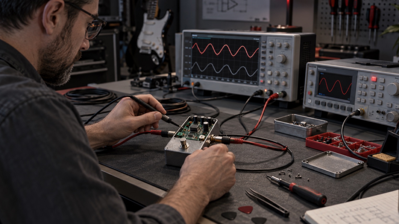
Editorial illustration: bypass approval should include level, loading, noise, headroom and power conditions.
Developing a private-label pedal range?
Send the intended effect type, bypass requirement, power format, enclosure, controls and target market through Contact Us. Available circuits and sample options must be confirmed for the project.
Switching pop, click and temporary mute
Players often describe several different events as a “pop.” A mechanical sound from the footswitch is not the same as an electrical transient in the audio path. Test through an amplifier or recording interface and observe the waveform under repeatable conditions.
Electrical switching noise can come from DC at a switching contact, circuit bias, charge in capacitors, grounding or the switch architecture. A relay or electronic controller may use a short mute to reduce a transient, but a long interruption can feel unnatural. Define an acceptable result with a reference sample and test rig.
Operate the switch repeatedly after the pedal has been powered for different periods. Test first engagement after power-up, repeated switching, control extremes and power cycling. Include several samples because one quiet unit does not prove batch consistency.
Power-loss behavior must match the claim
A mechanical true-bypass pedal may pass audio without external power when bypassed, while its LED and effect do not operate. A relay-based design may default to bypass, effect-on or mute depending on the circuit. A buffered-bypass design typically needs power for the active path.
Do not assume. Disconnect power in both states and record the result. Repeat at falling supply voltage because brownout behavior can differ from an immediate disconnection. If the product is advertised as passing signal without power, make that a controlled functional test.
Protection against reverse polarity or unsuitable adapters should be evaluated against the intended product requirements, but packaging must not encourage unapproved supplies. Confirm connector type, polarity marking, voltage and current guidance.
Noise and grounding
Bypass tests should use a defined source, load, cable and power supply. Measure or compare residual noise with the input terminated appropriately, then test with a representative guitar. A noisy environment can obscure differences; a laboratory result alone may miss grounding issues on a real pedalboard.
Inspect jack grounding, enclosure connection, cable routing and PCB layout. High-current LED or switching lines should not create avoidable interference in the audio path. Potentiometer grounds and shield strategy should follow the approved design.
A buffer can be quiet or noisy, just as a true-bypass pedal can have clean or unreliable contacts. The architecture is not a substitute for layout and production control.
Level-match the listening comparison
A small level increase often sounds clearer or more detailed. Before judging tone, measure the bypassed level and match monitoring volume where practical. Test a short cable directly to the amplifier, the pedal in bypass, and a representative multi-pedal chain.
Use several guitars if the product serves passive single-coil, passive humbucker and active-pickup users. Record cable lengths, pickup types and amplifier or interface input. Evaluate high-frequency response, low-frequency stability, transient behavior, noise and feel without relying on one adjective.
Where a buffer is intended to compensate for a long cable, test both short and long configurations. That demonstrates the use case without claiming that a buffer improves every rig.
Pedalboard order and sensitive circuits
Some vintage-style fuzz, wah or other circuits can interact strongly with the source impedance of a passive pickup. Placing a buffer ahead of them may change cleanup, gain or frequency response. This is a design interaction, not proof that all buffers are undesirable.
If a product range includes such circuits, create a compatibility test matrix. Evaluate the bypassed pedal and effect-on behavior before and after representative buffers. Product instructions can then describe tested guidance without universal claims.
For distributors, this is also a range-planning issue. A line containing only true-bypass pedals may still need a dedicated buffer or a buffered tuner for large boards. A line containing several always-buffered pedals should disclose the architecture so players can plan order.
Footswitch, relay and component durability
The switching part is a high-use component. Confirm the exact footswitch or relay specification, mounting method, nut torque or PCB support, and approved source. The supplier should define an endurance test appropriate to the design and verify function after cycling.
Cycle count alone is not enough if the actuator load is unrealistic. The fixture should press the switch in a representative direction and force. After cycling, inspect audio continuity, contact resistance where relevant, LED behavior, mechanical looseness and intermittent operation.
For relay systems, also test the control button, microcontroller or logic circuit, memory behavior where applicable and recovery after rapid power cycling.
Sample approval sequence
Use a controlled sequence:
- Confirm enclosure, controls, jacks, bypass architecture and basic effect direction.
- Approve circuit tuning and compare bypass behavior in the reference chain.
- Review a production-representative sample with final components and PCB.
- Build a pilot lot and test several units for noise, switching and level.
- Sign a golden sample, specification, test method and packaging artwork.
Record changes between rounds. A supplier may solve switching noise by changing a resistor, capacitor, relay timing or wiring. That improvement must be captured in the final bill of materials and revision.
Production and batch testing
Every finished pedal should receive a functional test appropriate to its risk and production process. Check effect-on audio, bypass audio, controls, footswitch, LED, jacks and power. Where the product claim depends on power-free bypass, test that condition.
Batch sampling can add measurements for bypass level, frequency response, noise and current consumption. Define fixtures and limits from approved design data. Use fixed cable lengths and loads. Track results by lot and identify reworked units.
Visual inspection should cover enclosure finish, printing, knob alignment, hardware, jack position, scratches and label accuracy. Cosmetic approval does not replace an audio test.
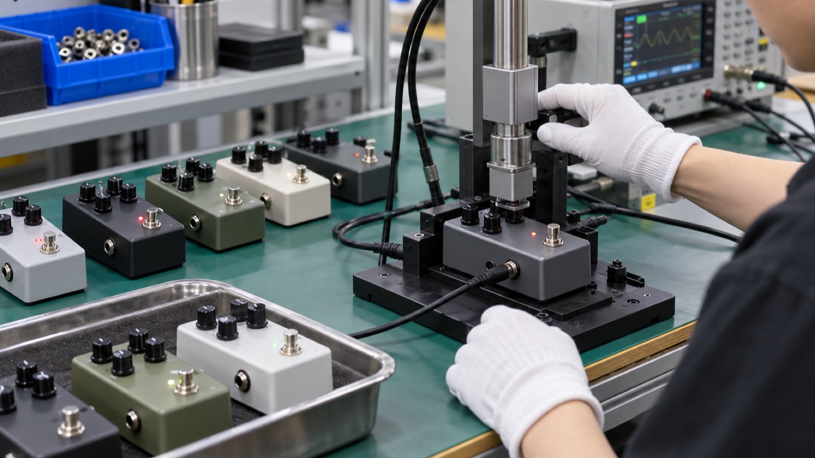
Editorial illustration: a wholesale program needs repeatable bypass, audio, hardware and cosmetic checks across the batch.
Packaging and product-page language
State the bypass type accurately. If a pedal uses a relay that provides a true-bypass audio path, the description can explain that architecture. If a buffer is always active, disclose it instead of using ambiguous wording.
Include approved power information, connector polarity, current requirement, control descriptions and signal-chain notes. Avoid absolute claims such as “zero tone loss,” “completely transparent” or “silent switching” unless the statement is defined and supported under specific conditions.
Retail packaging should protect footswitches, knobs and jacks. Factory bulk packaging should prevent enclosure-to-enclosure contact and keep accessories from scratching the finish.
Commercial comparison for wholesale buyers
Normalize quotations by circuit, bypass method, footswitch or relay, enclosure, PCB, jacks, pots, knobs, power protection, artwork, packaging and testing. A lower unit price may exclude a more durable switch, printed packaging or the inspection plan used for the sample.
Confirm MOQ by circuit and finish, sample charges, artwork setup, packaging scope and spare-parts support. Ask how component substitutions are controlled. Switching parts, audio semiconductors, pots and jacks should not change without review where they affect the approved design.
Common sourcing mistakes
Treating true bypass as a complete quality claim
It describes a bypass architecture, not the effect sound, switch durability, noise or assembly quality.
Assuming every buffer improves every pedalboard
A buffer can help drive cables, but placement and circuit quality matter. Test representative chains.
Ignoring power-off behavior
Relay and buffered systems may react differently from mechanical true bypass. Verify the exact product.
Approving one quiet sample
Switching transients and noise can vary. Test multiple pilot units and repeat switching under controlled conditions.
Publishing absolute “no tone loss” language
Every real signal chain has measurable behavior. Use specific, supportable descriptions.
Frequently asked questions
Is true bypass always better for guitar tone?
No. It can remove active circuitry from the bypassed path, but long cables and many connections can still load passive pickups. A suitable buffer can help in those conditions.
Does buffered bypass mean the effect is partly on?
Not necessarily. The effect processing can be bypassed while a separate active buffer remains in the signal path.
Can a true-bypass pedal pass audio without power?
Many mechanical designs can when bypassed, but relay or electronic implementations may behave differently. Test and specify the actual design.
Where should a buffer go on a pedalboard?
It depends on cable length and the pedals used. Some impedance-sensitive circuits may behave differently after a buffer, so evaluate the intended chain.
What should a wholesale buyer test?
Test bypass and effect levels, frequency behavior, noise, switching transient, power-off behavior, current, jack and switch reliability, control function and batch variation.
Should bypass type appear on packaging?
Yes, when it helps users plan their signal chain. The description should match the verified architecture and avoid unsupported absolutes.
Conclusion
True bypass and buffered bypass solve different signal-chain needs. The correct wholesale decision comes from the pedal’s target use, cable environment, interaction with other effects, switching behavior and production capability. Specify the architecture, measure loading and level, test power and switching conditions, approve a production-representative sample and control critical components.
Explore SoundSentry’s guitar effects pedal category and send your sourcing brief with the effect type, bypass requirement, power format, enclosure and target market. Available circuits, samples and commercial terms must be confirmed for the selected program.
Plan Your OEM/ODM Project
Share your target product, market, estimated quantity, branding, packaging and certification requirements with the SoundSentry Technical Team.
View Related Products Request Product Information or a Quote